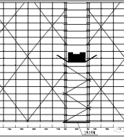
Positioning at a fixed distance, setting out the position of the cantilever beam and marking it properly. The cantilever beam must ensure sufficient anchoring strength and section buckling resistance, and the cantilever length should be determined according to the design. When the ordinary main beam is cantilever, the upright pole is directly supported on the cantilever beam, and the longitudinal spacing of the horizontal cantilever beam is the same as the longitudinal spacing of the upper scaffold upright pole; The upper scaffolding pole and cantilever beam support structure should have reliable positioning and connection measures to ensure the stability of the upper scaffolding body. Usually, welding 150-200mm with outer diameter is used on cantilever beams or longitudinal connecting beams Φ 40mm steel pipe or outer diameter Φ A 25mm steel bar is placed on the outside of the upright pole, and a sweeping rod is also installed at the bottom of the upright pole..
The horizontal cantilever beam must ensure sufficient anchoring strength and section buckling resistance. The longitudinal spacing of the horizontal cantilever beam is the same as the longitudinal spacing of the upper scaffolding pole, and the pole is directly supported on the cantilever beam. The upper scaffolding pole and cantilever beam support structure should have reliable positioning and connection measures to ensure the stability of the upper scaffolding body. Usually, welding 150-200mm with outer diameter is used on cantilever beams or longitudinal steel beams φ A 25mm steel bar is installed on the outside of the upright pole, and a sweeping rod is also installed at the bottom of the upright pole. As shown in the figure below.
Special site treatment measures: Here is a free download of construction technology materials.
The overhanging I-beams at the external corners of the structure intersect, and the length of the extending end cannot be guaranteed. If the length of the overhanging end is greater than 1.5, the I-beams on both sides are welded to the external corners at the intersection, with -200 × 200 × 10mm steel plates added on both sides. All contact points must be fully welded, and the height of the welding foot must not be less than 8mm, and there should be no air holes, slag inclusions, or missed welding..


